

Understanding Heat Pump Systems

Heat pump systems are efficient heating and cooling solutions that transfer heat between indoor and outdoor environments. They consist of several key components working together to maintain comfortable temperatures year-round.
Components and Functions
Heat pumps have four main components: the compressor, condenser, expansion valve, and evaporator. The compressor pressurizes refrigerant, raising its temperature. The condenser releases heat to the desired space.
The expansion valve reduces refrigerant pressure, cooling it down. The evaporator absorbs heat from the surrounding air or ground. These components work in a cycle, moving heat in or out of a building as needed.
Additional parts include the reversing valve, which switches between heating and cooling modes. Fans circulate air over the indoor and outdoor coils. The thermostat controls system operation based on temperature settings.
Control Board Basics
The control board is the brain of a heat pump system, coordinating its various functions. It processes input signals and sends commands to manage the heating and cooling cycles.
The Role of the Control Board
Control boards regulate heat pump operation by monitoring sensors and activating components. They interpret thermostat signals to start or stop heating and cooling cycles. These boards also manage defrost cycles and auxiliary heat during extreme cold.
Control boards protect the system by shutting it down if unsafe conditions occur. They monitor refrigerant pressures, temperatures, and electrical current draw. When issues arise, the board may trigger error codes to aid in diagnostics.
Many modern control boards offer advanced features like self-diagnostics and Wi-Fi connectivity. This allows for remote monitoring and adjustments to optimize performance and energy efficiency.
Don’t Overpay for HVAC Services – Call 888-894-0154 Now to Compare Local Quotes!
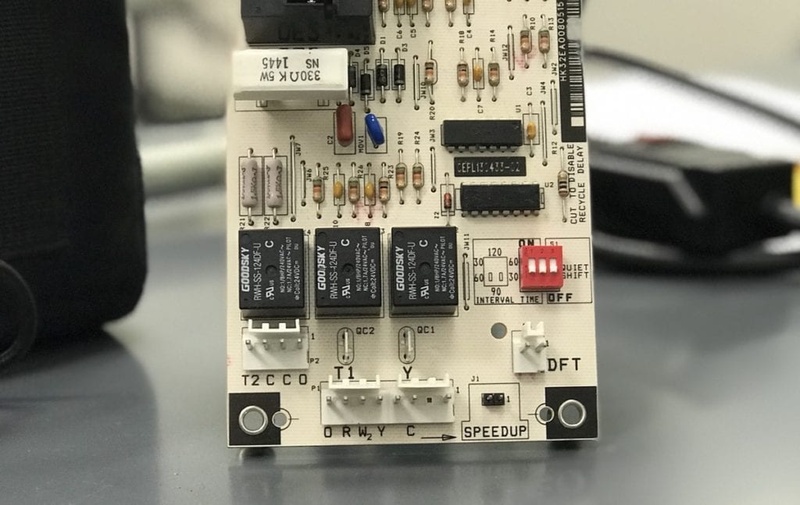
Anatomy of a Heat Pump Control Board
A typical heat pump control board consists of several key components:
- Microprocessor: Executes programmed logic and decision-making
- Relays: Switch high-voltage components on and off
- Fuses: Protect against electrical overloads
- Terminals: Connect to various system components and sensors
- LED indicators: Display system status and error codes
Control boards often include diagnostic ports for technician access. These allow for detailed system analysis and firmware updates when needed.
The board’s circuitry is designed to withstand temperature extremes and electrical noise. Conformal coatings protect against moisture and corrosion, ensuring reliability in various environments.
Diagnostic Tools and Equipment
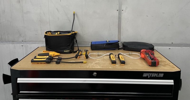
Effective troubleshooting of heat pump control boards requires specific tools and equipment. These resources enable technicians to accurately identify and resolve issues.
Multimeters and Their Use
Multimeters are essential for diagnosing heat pump control board problems. These versatile instruments measure voltage, current, and resistance. Technicians use multimeters to check power supply, verify component functionality, and detect faulty connections.
When testing a control board, technicians set the multimeter to the appropriate mode. They then probe specific points on the board to compare readings against manufacturer specifications. This process helps identify issues like short circuits, open circuits, or incorrect voltage levels.
Multimeters with advanced features like temperature sensing and capacitance measurement offer additional diagnostic capabilities. These functions can be particularly useful when assessing thermistors or capacitors on the control board.
Diagnostic Software Options
Specialized diagnostic software enhances heat pump control board troubleshooting. These programs interface with the control board to provide detailed system data and error codes.
Many manufacturers offer proprietary software for their heat pump models. Technicians connect a laptop or tablet to the control board using a dedicated interface cable. The software then displays real-time operating parameters, component status, and fault history.
Some diagnostic programs allow technicians to simulate various operating conditions. This feature helps identify intermittent issues that may not be present during normal operation.
Third-party diagnostic software options are also available. These tools often support multiple brands and models, offering a more versatile solution for technicians working with diverse equipment.
Common Heat Pump Malfunctions
Heat pumps can experience various issues that impact their performance and efficiency. These problems often stem from electrical components, thermostat functioning, or sensor failures.
Electrical Issues
Electrical problems frequently cause heat pump malfunctions. Faulty wiring or loose connections can lead to intermittent operation or complete system shutdown. Circuit breaker trips may indicate an overloaded system or short circuit.
Capacitor failures are another common electrical issue. A bad capacitor can prevent the compressor or fan motors from starting properly. Signs include a humming noise from the outdoor unit or the system failing to turn on.
Contactor problems can also disrupt heat pump operation. A worn or stuck contactor may prevent power from reaching the compressor or outdoor fan motor. This can result in the heat pump not heating or cooling effectively.
Thermostat Problems
Thermostat malfunctions can significantly impact heat pump performance. A faulty thermostat may send incorrect signals to the system, causing it to cycle on and off too frequently or not at all.
Calibration issues can lead to inaccurate temperature readings. This results in the heat pump running longer than necessary or not providing adequate heating or cooling. Proper thermostat placement is crucial for accurate temperature sensing.
Wiring problems between the thermostat and heat pump can cause communication errors. This may result in the system not responding to temperature changes or operating in the wrong mode.
Sensor Failures
Heat pumps rely on various sensors to operate efficiently. The defrost sensor monitors outdoor coil temperature and initiates the defrost cycle when necessary. A faulty defrost sensor can lead to ice buildup on the outdoor unit, reducing efficiency.
Don’t Overpay for HVAC Services – Call 888-894-0154 Now to Compare Local Quotes!
Temperature sensors in the indoor and outdoor units provide crucial data for system operation. Malfunctioning sensors can cause the heat pump to operate incorrectly, leading to inadequate heating or cooling.
Pressure sensors monitor refrigerant levels and system pressures. Failures in these sensors can result in improper refrigerant flow, potentially damaging the compressor or reducing overall system efficiency.
Troubleshooting Procedures
Effective troubleshooting of heat pump control boards requires a systematic approach. Following established procedures helps pinpoint issues quickly and accurately.
Initial System Assessment
Begin by visually inspecting the control board for obvious signs of damage. Look for burnt components, loose connections, or physical defects. Check the power supply to ensure proper voltage is reaching the board.
Verify all wiring connections are secure and free from corrosion. Examine fuses and circuit breakers for any that may have tripped.
Test the thermostat functionality and confirm it’s sending the correct signals to the control board. Measure the incoming power at the board terminals using a multimeter.
Step-by-Step Diagnosis
Start with the simplest potential causes and work towards more complex issues. Check the air filter and coils for blockages that could trigger error codes.
Test individual components connected to the control board, such as motors, sensors, and relays. Use a multimeter to verify continuity and resistance values.
Inspect capacitors for signs of bulging or leakage. Test their capacitance with a meter designed for this purpose.
Monitor the system through a complete heating and cooling cycle, noting any irregularities in operation or unusual noises.
Interpreting Diagnostic Codes
Consult the manufacturer’s manual for specific error code meanings. Most control boards use LED flash patterns to indicate different faults.
Common codes often relate to sensor failures, communication errors, or voltage issues. Record the exact sequence of flashes for accurate interpretation.
Some advanced systems may require a specialized diagnostic tool to access detailed fault information. This can provide valuable data on system performance and history.
Use the diagnostic codes as a starting point for further investigation, not as a definitive diagnosis. Verify the indicated issue through additional testing and observation.
Control Board Repairs
Repairing heat pump control boards requires specific techniques and careful component replacement. Proper soldering and part swapping can often restore functionality to malfunctioning boards.
Don’t Overpay for HVAC Services – Call 888-894-0154 Now to Compare Local Quotes!
Soldering Techniques
Soldering is crucial for control board repairs. Use a temperature-controlled soldering iron set to 315-370°C (600-700°F). Clean the board and components with isopropyl alcohol before soldering.
Apply flux to improve solder flow and prevent oxidation. Use lead-free solder with a 0.8mm diameter for most repairs. Hold the iron tip against both the pad and component lead for 2-3 seconds before adding solder.
Create a small, smooth solder joint without excess material. Allow joints to cool naturally. Inspect connections with a magnifying glass to ensure proper bonding.
Component Replacement
Identify faulty components through visual inspection and multimeter testing. Common failures include blown capacitors, burnt resistors, and damaged relays.
Order exact replacement parts matched to the board’s specifications. Use a solder sucker or desoldering braid to remove old components. Clean pads thoroughly before installing new parts.
Handle sensitive components like ICs with anti-static precautions. Align new parts precisely and solder carefully. Double-check polarity on capacitors and diodes.
Test the repaired board thoroughly before reinstalling. Verify voltage levels and signal outputs match manufacturer specifications.
Control Board Replacement
Replacing a faulty control board is a crucial step in restoring heat pump functionality. Proper selection and installation of the replacement board are essential for optimal system performance.
Selecting a Replacement Board
When choosing a replacement control board, compatibility is key. Check the model number and specifications of the original board to ensure an exact match. Verify that the new board supports all features of your heat pump system.
Consider purchasing from authorized dealers or directly from the manufacturer to guarantee authenticity and warranty coverage. Some boards may require programming or configuration before installation.
Examine the connectors, mounting points, and dimensions of the replacement board to confirm it will fit properly in your heat pump. If unsure, consult a professional HVAC technician for guidance on selecting the correct board.
Installation Guide
Before beginning installation, disconnect power to the heat pump at the circuit breaker. Remove the access panel and locate the control board. Take a photo of the existing wiring connections for reference.
Carefully disconnect all wires from the old board, labeling them if necessary. Remove any mounting screws and extract the faulty board. Place the new control board in position and secure it with screws.
Reconnect all wires to the corresponding terminals on the new board, referring to your photo or wiring diagram. Double-check all connections for accuracy and tightness. Replace the access panel and restore power to the system.
Test the heat pump’s operation to ensure proper functionality with the new control board. Monitor performance closely over the next few days to verify the replacement has resolved any previous issues.
Advanced Troubleshooting
Heat pump control board troubleshooting often requires advanced techniques to resolve complex issues. These methods help technicians pinpoint elusive problems and address unusual error codes.
Dealing with Intermittent Issues
Intermittent problems can be challenging to diagnose. Start by monitoring the system over an extended period. Use data logging equipment to record voltage fluctuations, temperature changes, and cycle patterns.
Check for loose connections that may cause sporadic malfunctions. Vibration can worsen these issues over time.
Thermal imaging cameras can detect hot spots on the control board, indicating potential component failures. Look for discolored or bulging capacitors, which often cause intermittent problems.
Test relays and contactors for proper operation. Faulty relays may work inconsistently, leading to puzzling system behavior.
Addressing Code Anomalies
Unusual error codes require systematic analysis. Begin by verifying the accuracy of sensors and thermistors. Faulty sensors can trigger incorrect error messages.
Cross-reference error codes with manufacturer documentation. Some codes may indicate multiple possible issues.
Use specialized diagnostic tools to communicate directly with the control board. These can provide detailed fault histories and real-time data.
Check for software updates. Manufacturers occasionally release firmware updates to address known bugs or improve system performance.
Consider environmental factors that may affect the control board. Excessive humidity or electromagnetic interference can cause unexpected behavior.
Professional Resources
Accessing expert help and ongoing training are crucial for HVAC technicians working with heat pump control boards.
When to Call a Professional
Complex control board issues often require specialized expertise. Technicians should contact manufacturers or certified professionals when:
• Diagnostic tools indicate multiple component failures
• Error codes are unfamiliar or inconsistent
• Repairs involve proprietary software or firmware updates
• Safety systems are malfunctioning
Attempting repairs beyond one’s skill level can void warranties or create hazards. Professional support ensures proper diagnosis and resolution of intricate control board problems.
Continuing Education for Technicians
HVAC technology evolves rapidly, necessitating ongoing training for technicians. Key educational resources include:
• Manufacturer-specific courses on new control board models
• Industry certifications like NATE (North American Technician Excellence)
• Online webinars and video tutorials from reputable HVAC organizations
• Technical workshops at trade shows and conferences
Regular skill updates help technicians stay current with the latest heat pump control board technologies and troubleshooting techniques. This knowledge enhances diagnostic accuracy and repair efficiency.
How to Avoid Being Ripped Off and Get a Fair Repair Price
Finding the right heat pump repair expert can be tricky—some companies offer rock-bottom prices because they’re inexperienced or have poor reputations, while others charge far too much for the same work. That’s why the smartest way to get quality repairs at a fair price is to compare estimates from top-rated local pros. Meet with each, learn about their history and the experience of the technicians that will do the work. Choose an experienced heat pump repair contractor with reasonable rates. You can expedite this process by using our Free Local Estimates service.
When you fill out a quick form and submit it, you’ll soon be contacted by three of the top heat pump repair and installation companies near you. They are prescreened for experience, and all are licensed and insured for your protection. Click below to get started and protect your home and wallet today.
Frequently Asked Questions
Heat pump control board issues can manifest in various ways. Proper diagnosis and safety procedures are crucial when troubleshooting these components. Using the right tools and techniques helps pinpoint problems accurately.
What are the common symptoms indicating a faulty heat pump control board?
A faulty control board often causes erratic system behavior. This may include the heat pump failing to turn on or off, inconsistent heating or cooling, and unusual noises during operation.
Error codes displayed on the thermostat can also signal control board problems. In some cases, the system may short cycle or fail to respond to thermostat commands.
Which diagnostic steps should be taken to confirm a control board malfunction in a heat pump?
Visual inspection is the first step in diagnosing control board issues. Look for signs of physical damage, burnt components, or loose connections.
Check the LED status lights on the board. These often provide valuable diagnostic information. Consult the manufacturer’s manual to interpret the light patterns.
Testing voltage outputs at various terminals can help identify specific malfunctions. This requires a multimeter and knowledge of the correct voltage readings.
Is there a way to reset a heat pump control board, and how often should this be done?
Many control boards have a reset button or procedure. Typically, this involves disconnecting power for a few minutes before reconnecting.
Resets should only be performed when troubleshooting specific issues. Frequent resets are not recommended and may indicate underlying problems that need addressing.
Always consult the manufacturer’s instructions before attempting a reset. Improper procedures can potentially damage the system.
What are the proper safety procedures for replacing a heat pump circuit board?
Always disconnect power to the unit before working on the control board. Use a voltage tester to confirm the absence of electrical current.
Wear protective gear, including insulated gloves and safety glasses. Static electricity can damage sensitive components, so use an anti-static wrist strap.
Document the wiring connections before removal. Take photos or make detailed notes to ensure correct reinstallation of the new board.
How can a multimeter be used to test the functionality of a furnace control board?
Set the multimeter to the appropriate voltage range for the component being tested. For AC voltage, use the VAC setting.
Test input voltage at the main power terminals. This should match the unit’s rated voltage. Check for continuity on fuses and other protective devices.
Measure voltage outputs at various terminals while the system runs through its cycles. Compare readings to the manufacturer’s specifications.
What is the typical process for diagnosing issues with an HVAC control panel?
Start by verifying proper power supply to the control panel. Check for any visible damage or loose connections.
Review error codes or LED indicators on the panel. These often provide specific diagnostic information about system issues.
Test individual components connected to the panel, such as sensors and relays. Ensure they are functioning correctly and sending proper signals.
Use a multimeter to check voltage outputs at different terminals. Compare these readings to the expected values in the system’s wiring diagram.

How to Get the Best HVAC Prices
- Firstly, keep in mind that installation quality is always the most important thing for residential HVAC project. So never sacrifice contractor quality for a lower price.
- Secondly, remember to look up the latest rebates as we talked above.
- Thirdly, ask for at least 3 bids before you make the decision. You can click here to get 3 free estimates from your local contractors, and this estimate already takes rebates and tax credit into consideration and filter unqualified contractors automatically.
Lastly, once you chose the right contractor, remember to use the tactics from this guide: Homeowners Tactics When Negotiating with HVAC Dealer to get the final best price.